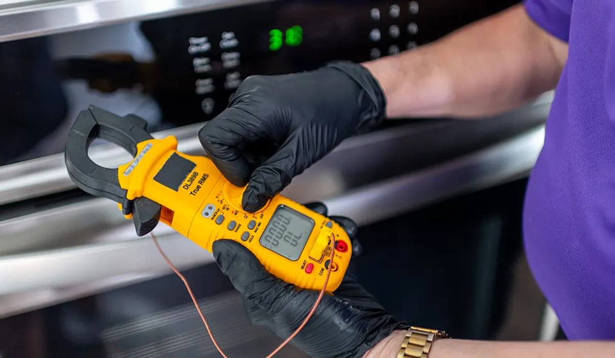
A multimeter is the difference between guessing and knowing. Instead of replacing parts one by one, you test each component and find the one that has failed. This guide covers the three tests that matter for appliances, in the order you should run them.
The golden rule: voltage tests are done live, everything else is done with the appliance unplugged.
- Test 1 — Voltage: is power reaching the component? Done live, with care.
- Test 2 — Continuity: is the path unbroken? Done unplugged.
- Test 3 — Resistance: is the component within spec? Done unplugged.
- Capacitance: a fourth test for start/run capacitors.
- Safety: unplug, discharge capacitors, and use a CAT III meter.
Safety first
- Unplug the appliance for every test except voltage.
- Discharge capacitors before touching them — they hold a charge.
- Use a CAT III 600V meter and check your leads for cracks.
- Never test resistance on a live circuit — it gives a meaningless reading and can damage the meter.
- Keep one hand behind your back when probing live voltage, so current cannot cross your chest.
Test 1: voltage
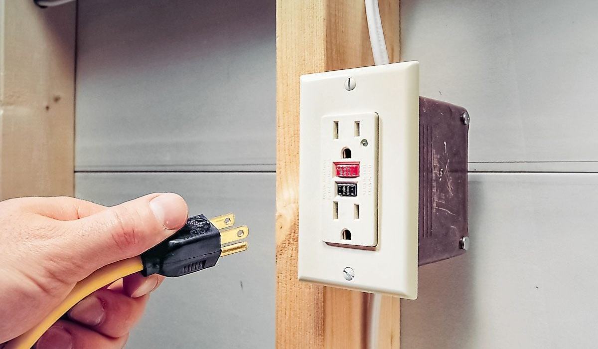
Voltage testing answers one question: is power getting to this component? Set the meter to AC voltage (or DC for control boards), and probe across the component's terminals while the appliance is plugged in and switched on.
| Reading | Meaning | Next step |
|---|---|---|
| ~120V AC | Power is present | Fault is downstream — test the component |
| 0V | No power reaching it | Trace back: fuse, switch, board |
| Low/fluctuating | Bad connection or failing board | Check terminals and wiring |
Do not attempt voltage testing unless you are comfortable working near live mains. If you are not, unplug the appliance and use continuity and resistance tests instead — they find most faults without any live work.
Test 2: continuity
Continuity testing checks whether a path is unbroken. Set the meter to continuity (the beep symbol), unplug the appliance, and touch the probes to both ends of the component. A beep means the path is complete; silence means it is broken.
| Component | Expected | If it fails |
|---|---|---|
| Thermal fuse | Beep (continuity) | Blown — replace |
| Door switch | Beep when closed | Replace switch |
| Heating element | Beep (some resistance) | Open — replace |
| Wire/harness | Beep end to end | Broken wire — repair |
| Thermostat | Beep when cold | Replace if open |
Test 3: resistance
Resistance testing measures how much a component resists current, in ohms. It confirms a component is within specification rather than simply open or closed. Unplug the appliance, set the meter to ohms, and probe across the component.
| Component | Typical reading | Interpretation |
|---|---|---|
| Heating element | 10–50 ohms | Within range = good |
| Motor winding | A few ohms | Open = failed |
| Thermistor | Varies with temp | Compare to spec chart |
| Solenoid coil | Hundreds of ohms | Open = failed |
| Capacitor | Charges then climbs | No movement = failed |
Reading the results
The pattern to remember: a component that should conduct but does not is open (failed). A component that should not conduct but does is shorted (failed). A component that reads wildly outside its spec is failing. Everything else is probably fine, and the fault is elsewhere.
- Open circuit (no continuity, infinite resistance) = broken component.
- Short circuit (continuity where there should be none) = failed component.
- Out of spec = failing component, replace it.
- In spec = component is fine; look elsewhere.
- Intermittent = test again while wiggling wires; a loose connection can read fine when still.
Use voltage to confirm power is present, continuity to find broken paths, and resistance to check components against spec. Unplug for everything except voltage, discharge capacitors, and use a CAT III meter. Three tests find almost every appliance fault.
Frequently asked questions
Diagnostic tools
An auto-ranging meter with capacitance covers every appliance test.