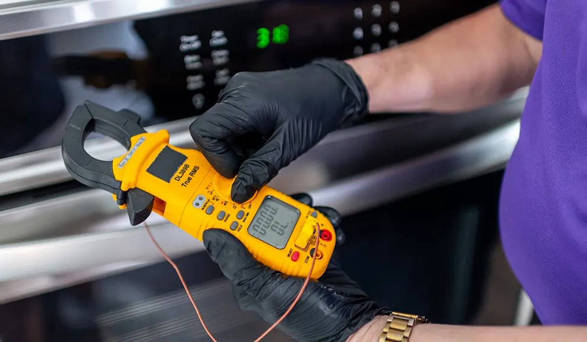
A multimeter turns appliance repair from guesswork into diagnosis. Instead of replacing parts until the fault goes away, you test the four or five components that actually fail and replace the one that has failed.
These are the five tests that cover the overwhelming majority of domestic appliance faults, in the order you should run them.
- Outlet test — is the appliance even getting power?
- Continuity test — has a thermal fuse or safety link blown?
- Resistance test — is the heating element or thermostat open?
- Winding test — is the compressor or motor winding open or shorted?
- Capacitance test — has the start/run capacitor failed?
On this page
Safety first
- Unplug the appliance before any resistance, continuity or capacitance test. These are all done dead.
- Only voltage tests are done live, and only with properly rated probes and a CAT III meter.
- Discharge capacitors before touching them. A run capacitor can hold a dangerous charge.
- Verify your meter works by touching the probes together — it should read near zero ohms and beep on continuity.
- Never rush a live measurement. One slip with a probe can short a board or burn you.
Setting up the meter
| Test | Dial setting | Probes |
|---|---|---|
| Outlet voltage | AC voltage, 200+ V range | Into the socket slots |
| Continuity | Continuity / beep mode | Across the component |
| Resistance | Ohms, auto or 20k range | Across the component |
| Capacitance | Capacitance range | Across the capacitor terminals |
| DC voltage | DC volts | Across the board terminals |
If your meter has auto-ranging, use it. Manually setting the range is a common source of wrong readings and of the meter being damaged by an over-range measurement.
1. Test the outlet
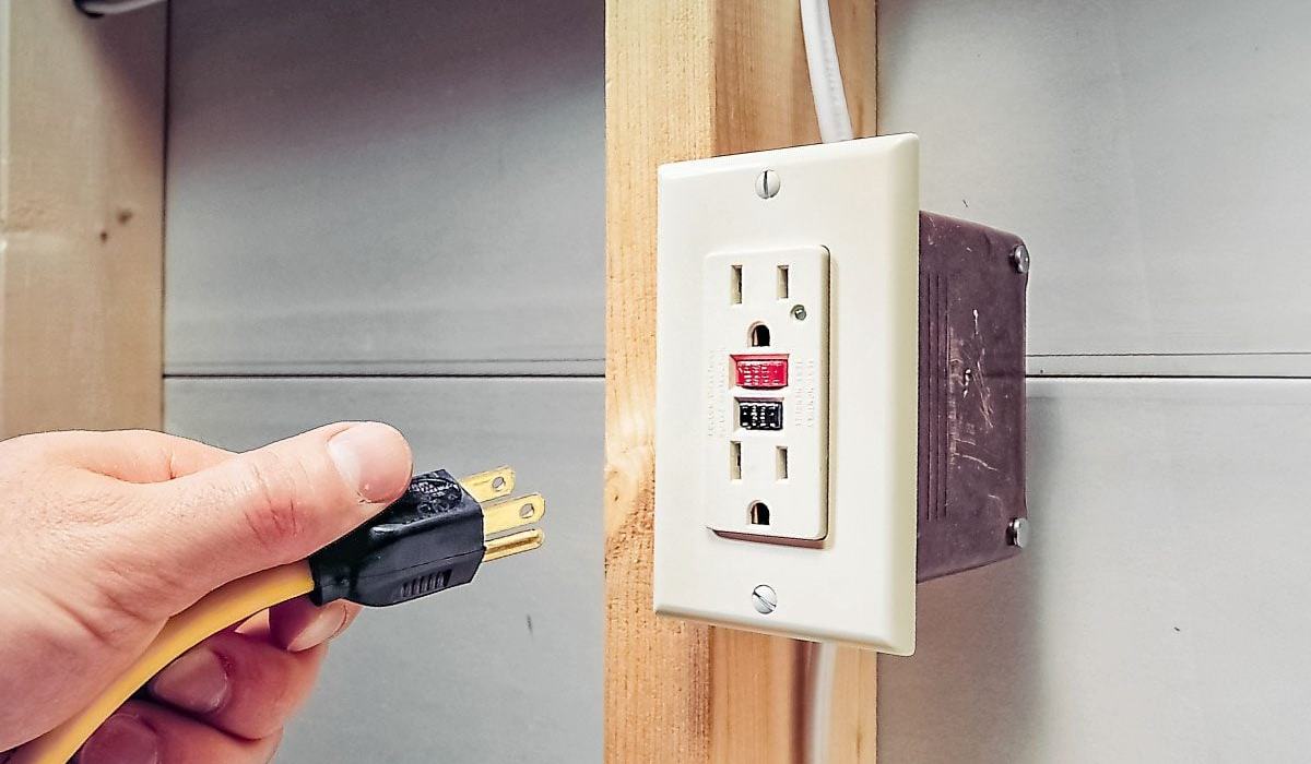
Before touching the appliance, confirm the supply. A surprising proportion of 'broken' appliances are plugged into a dead outlet.
- Set the meter to AC voltage, 200 V or higher.
- Insert the probes into the two socket slots — live and neutral.
- A domestic outlet should read 110–125 V AC in the US, or 220–240 V depending on region.
- If it reads zero, check the breaker and any upstream GFCI.
- If it reads low or unstable, the supply is the problem, not the appliance.
2. Continuity and thermal fuses
A thermal fuse is a one-time safety device that opens permanently when the appliance overheats. It is a very common failure and it is trivially testable.
- Unplug the appliance and discharge any capacitor.
- Set the meter to continuity/beep.
- Touch one probe to each end of the fuse.
- A beep means continuity — the fuse is good.
- No beep means the fuse is open and must be replaced with the identical temperature rating.
- Repeat for any safety link, door switch or interlock in the circuit.
A thermal fuse exists to prevent a fire. Replacing it with a wire, a higher-rated fuse or a piece of foil removes the protection that stopped the appliance overheating in the first place. Always fit the exact part number — and investigate why it blew.
3. Heating element and thermostat
Heating elements and thermostats both fail open, and both are simple resistance measurements.
- Unplug the appliance and isolate the component by removing one lead.
- Set the meter to resistance (ohms).
- Measure across the two terminals of the element.
- A working heating element reads a low but non-zero resistance — typically 10–50 ohms.
- Infinite reading (OL) means the element is open and must be replaced.
- Zero ohms means it is shorted — also a failure.
- For a thermostat: cold it should read near zero; warm it should read open. If the reading does not change with temperature, it has failed.
4. Compressor and motor windings
A compressor that hums but will not start, or a motor that does nothing, is frequently a winding failure. This is a diagnostic where the meter pays for itself immediately.
- Unplug the appliance. Discharge the capacitor.
- Remove the start relay and the overload protector from the compressor terminals.
- Identify the three pins: common, start and run.
- Measure common-to-start, common-to-run, and start-to-run.
- Each pair should show continuity with a low but non-zero resistance.
- An open reading on any pair indicates a failed winding — the compressor is done.
- A reading of near zero indicates a shorted winding — also failed.
- Additionally, check each pin to the compressor body: you should read infinite. Any continuity to the casing means the winding is grounded.
| Reading | Meaning | Action |
|---|---|---|
| Low resistance, all three pairs consistent | Windings healthy | Look elsewhere |
| Open (OL) on one pair | Broken winding | Compressor failed — replace unit |
| Near zero on any pair | Shorted winding | Compressor failed |
| Continuity from pin to casing | Grounded winding | Compressor failed |
| All pairs balanced relative to spec | Healthy | Test the capacitor and relay next |
5. Capacitors
A failed start or run capacitor is one of the most common causes of a compressor or motor that will not start, and it is the cheapest part in the circuit to replace.
- Unplug the appliance and discharge the capacitor safely with an insulated resistor or screwdriver across the terminals.
- Note the rated microfarad value printed on the capacitor.
- Set the meter to capacitance if it has that range.
- Measure across the terminals and compare with the rating.
- Within roughly ±10% of the printed value means it is healthy.
- Significantly low means it has lost capacitance and must be replaced.
- Zero or OL means it is open or shorted — replace it.
- A capacitor that reads correct on capacitance can still fail under load, but loss of capacitance is the common mode.
A capacitor holds charge even with the appliance unplugged. Short the terminals through an insulated resistor before touching them. A charged run capacitor gives a painful shock and can damage your meter.
Reading the results
| Measurement | Good reading | Failed reading | Most likely part |
|---|---|---|---|
| Outlet AC voltage | 110–125 V (US) | 0 V | Supply, breaker or GFCI |
| Thermal fuse continuity | Beep | No beep | Thermal fuse |
| Heating element resistance | 10–50 ohms | OL or 0 ohms | Element |
| Compressor windings | Consistent low ohms | OL or near 0 | Compressor |
| Capacitance | Within ±10% | Low or OL | Capacitor |
Test the outlet, then the thermal fuse, then the element or thermostat, then the windings, then the capacitor. In that order you will identify the fault on the first attempt most of the time — and you will stop replacing parts that were never broken.